Which Two Gre Features Can You Configure to Prevent Fragmentation (Choose Two)
This document describes how IPv4 Fragmentation and Path Maximum Transmission Unit Discovery (PMTUD) work and also discusses some scenarios that involves the behavior of PMTUD when combined with different combinations of IPv4 tunnels. The current widespread use of IPv4 tunnels in the Net has brought the problems that involve IPv4 Fragmentation and PMTUD to the forefront.
The IPv4 protocol was designed for employ on a wide variety of transmission links. Although the maximum length of an IPv4 datagram is 65535, well-nigh transmission links enforce a smaller maximum parcel length limit, called an MTU. The value of the MTU depends on the blazon of the transmission link. The design of IPv4 accommodates MTU differences since it allows routers to fragment IPv4 datagrams as necessary. The receiving station is responsible for the reassembly of the fragments back into the original full size IPv4 datagram.
IPv4 fragmentation involves to suspension a datagram into a number of pieces that tin can be reassembled afterward. The IPv4 source, destination, identification, total length, and fragment offset fields, along with the "more fragments" and "don't fragment" flags in the IPv4 header, are used for IPv4 fragmentation and reassembly. For more information about the mechanics of IPv4 fragmentation and reassembly, see RFC 791.
This paradigm depicts the layout of an IPv4 header.

The identification is xvi bits and is a value assigned by the sender of an IPv4 datagram in order to aid in the reassembly of the fragments of a datagram.
The fragment offset is thirteen $.25 and indicates where a fragment belongs in the original IPv4 datagram. This value is a multiple of eight bytes.
In the flags field of the IPv4 header, there are 3 bits for control flags. It is of import to note that the "don't fragment" (DF) bit plays a fundamental role in PMTUD because information technology determines whether or non a packet is immune to be fragmented.
Fleck 0 is reserved, and is ever set to 0. Scrap 1 is the DF chip (0 = "may fragment", 1 = "do not fragment"). Bit 2 is the MF bit (0 = "final fragment," 1 = "more than fragments").
| Value | Bit 0 Reserved | Chip one DF | Bit 2 MF |
|---|---|---|---|
| 0 | 0 | May | Last |
| 1 | 0 | Do not | More |
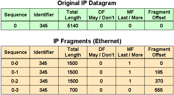
The next graphic shows an example of fragmentation. If you add up all the lengths of the IPv4 fragments, the value exceeds the original IPv4 datagram length by threescore. The reason that the overall length is increased by threescore is considering three additional IPv4 headers were created, one for each fragment subsequently the first fragment.
The first fragment has an showtime of 0, the length of this fragment is 1500; this includes 20 bytes for the slightly modified original IPv4 header.
The second fragment has an start of 185 (185 x viii = 1480), which ways that the data portion of this fragment starts 1480 bytes into the original IPv4 datagram. The length of this fragment is 1500; this includes the additional IPv4 header created for this fragment.
The third fragment has an offset of 370 (370 ten eight = 2960), which means that the data portion of this fragment starts 2960 bytes into the original IPv4 datagram. The length of this fragment is 1500; this includes the additional IPv4 header created for this fragment.
The quaternary fragment has an outset of 555 (555 x 8 = 4440), which means that the data portion of this fragment starts 4440 bytes into the original IPv4 datagram. The length of this fragment is 700 bytes; this includes the additional IPv4 header created for this fragment.
It is only when the last fragment is received that the size of the original IPv4 datagram can exist determined.
The fragment offset in the final fragment (555) gives a data offset of 4440 bytes into the original IPv4 datagram. If you then add together the data bytes from the last fragment (680 = 700 - 20), that gives you 5120 bytes, which is the data portion of the original IPv4 datagram. Then, addition of twenty bytes for an IPv4 header equals the size of the original IPv4 datagram (4440 + 680 + 20 = 5140) as shown in the images.
Problems with IPv4 Fragmentation
At that place are several bug that make IPv4 fragmentation undesirable. There is a modest increment in CPU and retentivity overhead in order to fragment an IPv4 datagram. This holds true for the sender as well as for a router in the path between a sender and a receiver. The cosmos of fragments but involves to create fragment headers and copy the original datagram into the fragments. This can be done adequately efficiently because all the information needed in order to create the fragments is immediately bachelor.
Fragmentation causes more overhead for the receiver when reassembling the fragments because the receiver must classify memory for the arriving fragments and coalesce them back into one datagram after all of the fragments are received. Reassembly on a host is not considered a problem because the host has the time and retentivity resources in social club to devote to this job.
Only, reassembly is very inefficient on a router whose primary task is to frontwards packets equally quickly equally possible. A router is not designed to hold on to packets for whatever length of fourth dimension. Too, a router that does reassembly chooses the largest buffer available (18K) with which to work considering it has no way to know the size of the original IPv4 package until the terminal fragment is received.
Another fragmentation issue involves how dropped fragments are handled. If one fragment of an IPv4 datagram is dropped, and so the entire original IPv4 datagram must exist resent, and it is likewise fragmented. You come across an example of this with Network File System (NFS). NFS, past default, has a read and write cake size of 8192, so a NFS IPv4/UDP datagram is approximately 8500 bytes (which includes NFS, UDP, and IPv4 headers). A sending station connected to an Ethernet (MTU 1500) has to fragment the 8500 byte datagram into vi pieces; 5 1500 byte fragments and 1 1100 byte fragment. If any of the six fragments are dropped considering of a congested link, the complete original datagram has to be retransmitted, which means that six more fragments will have to be created. If this link drops 1 in half-dozen packets, then the odds are depression that whatsoever NFS data can be transferred over this link, since at least one IPv4 fragment would be dropped from each NFS 8500 byte original IPv4 datagram.
Firewalls that filter or manipulate packets based on Layer 4 (L4) through Layer 7 (L7) information in the packet might have trouble processing IPv4 fragments correctly. If the IPv4 fragments are out of order, a firewall might block the non-initial fragments because they practise non carry the information that would friction match the packet filter. This would mean that the original IPv4 datagram could not exist reassembled past the receiving host. If the firewall is configured to allow not-initial fragments with insufficient information to properly match the filter, then a non-initial fragment set on through the firewall could occur. Also, some network devices (such every bit Content Switch Engines) directly packets based on L4 through L7 information, and if a packet spans multiple fragments, then the device might accept trouble enforcing its policies.
Avoid IPv4 Fragmentation: What TCP MSS Does and How Information technology Works
The TCP Maximum Segment Size (MSS) defines the maximum corporeality of information that a host is willing to accept in a single TCP/IPv4 datagram. This TCP/IPv4 datagram might be fragmented at the IPv4 layer. The MSS value is sent as a TCP header option only in TCP SYN segments. Each side of a TCP connection reports its MSS value to the other side. Contrary to popular conventionalities, the MSS value is not negotiated between hosts. The sending host is required to limit the size of data in a single TCP segment to a value less than or equal to the MSS reported by the receiving host.
Originally, MSS meant how big a buffer (greater than or equal to 65496 bytes) was allocated on a receiving station to be able to shop the TCP information independent within a single IPv4 datagram. MSS was the maximum segment (chunk) of data that the TCP receiver was willing to accept. This TCP segment could exist every bit large equally 64K (the maximum IPv4 datagram size) and it could be fragmented at the IPv4 layer in club to exist transmitted across the network to the receiving host. The receiving host would reassemble the IPv4 datagram earlier it handed the complete TCP segment to the TCP layer.
Here are a couple of scenarios that testify how MSS values are fix and used to limit TCP segment sizes, and therefore, IPv4 datagram sizes.
Scenario 1 illustrates the style MSS was first implemented. Host A has a buffer of 16K and Host B a buffer of 8K. They ship and receive their MSS values and adjust their send MSS for sending data to each other. Notice that Host A and Host B will accept to fragment the IPv4 datagrams that are larger than the interface MTU, but withal less than the send MSS considering the TCP stack could pass 16K or 8K bytes of data down the stack to IPv4. In Host B's example, packets could exist fragmented twice, once to get onto the Token Ring LAN and again to get onto the Ethernet LAN.
Scenario one

- Host A sends its MSS value of 16K to Host B.
- Host B receives the 16K MSS value from Host A.
- Host B sets its send MSS value to 16K.
- Host B sends its MSS value of 8K to Host A.
- Host A receives the 8K MSS value from Host B.
- Host A sets its transport MSS value to 8K.
In order to assist in avoiding IPv4 fragmentation at the endpoints of the TCP connexion, the selection of the MSS value was changed to the minimum buffer size and the MTU of the outgoing interface (- twoscore). MSS numbers are forty bytes smaller than MTU numbers considering MSS is simply the TCP data size, which does not include the 20 byte IPv4 header and the 20 byte TCP header. MSS is based on default header sizes; the sender stack must subtract the appropriate values for the IPv4 header and the TCP header dependent on what TCP or IPv4 options are used.
The way MSS now works is that each host volition first compare its approachable interface MTU with its own buffer and choose the lowest value every bit the MSS to send. The hosts will then compare the MSS size received against their own interface MTU and once again cull the lower of the two values.
Scenario 2 illustrates this boosted stride taken by the sender in order to avoid fragmentation on the local and remote wires. Observe how the MTU of the outgoing interface is taken into business relationship past each host (before the hosts send each other their MSS values) and how this helps to avoid fragmentation.
Scenario 2
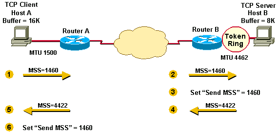
- Host A compares its MSS buffer (16K) and its MTU (1500 - forty = 1460) and uses the lower value as the MSS (1460) to send to Host B.
- Host B receives Host A's send MSS (1460) and compares it to the value of its outbound interface MTU - xl (4422).
- Host B sets the lower value (1460) every bit the MSS in order to send IPv4 datagrams to Host A.
- Host B compares its MSS buffer (8K) and its MTU (4462-40 = 4422) and uses 4422 as the MSS to ship to Host A.
- Host A receives Host B'south send MSS (4422) and compares information technology to the value of its outbound interface MTU -xl (1460).
- Host A sets the lower value (1460) as the MSS for sending IPv4 datagrams to Host B.
1460 is the value called by both hosts as the send MSS for each other. Oftentimes the send MSS value volition exist the same on each end of a TCP connection.
In Scenario ii, fragmentation does not occur at the endpoints of a TCP connection because both outgoing interface MTUs are taken into business relationship by the hosts. Packets tin can nevertheless become fragmented in the network between Router A and Router B if they encounter a link with a lower MTU than that of either hosts' outbound interface.
TCP MSS equally described earlier takes intendance of fragmentation at the two endpoints of a TCP connection, but it does non handle the case where there is a smaller MTU link in the center between these two endpoints. PMTUD was adult in order to avoid fragmentation in the path betwixt the endpoints. It is used to dynamically determine the lowest MTU forth the path from a packet's source to its destination.
Note: PMTUD is only supported past TCP and UDP. Other protocols do not back up it. If PMTUD is enabled on a host, and information technology near ever is, all TCP and UDP packets from the host will have the DF bit fix.
When a host sends a full MSS data packet with the DF fleck set, PMTUD reduces the send MSS value for the connection if it receives information that the packet would crave fragmentation. A host unremarkably "remembers" the MTU value for a destination since information technology creates a "host" (/32) entry in its routing tabular array with this MTU value.
If a router tries to forward an IPv4 datagram, with the DF fleck set, onto a link that has a lower MTU than the size of the bundle, the router drops the packet and render an Net Control Message Protocol (ICMP) "Destination Unreachable" message to the source of this IPv4 datagram, with the code that indicates "fragmentation needed and DF prepare" (type iii, lawmaking 4). When the source station receives the ICMP bulletin, information technology will lower the ship MSS, and when TCP retransmits the segment, information technology will use the smaller segment size.
Hither is an instance of an ICMP "fragmentation needed and DF set up" message that you might run across on a router after the debug ip icmp command is turned on:
ICMP: dst (10.ten.10.10) frag. needed and DF set unreachable sent to 10.i.1.1
This diagram shows the format of ICMP header of a "fragmentation needed and DF set" "Destination Unreachable" message.
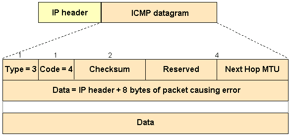
Per RFC 1191, a router that returns an ICMP message which indicates "fragmentation needed and DF set" must include the MTU of that next-hop network in the low-order 16 $.25 of the ICMP additional header field that is labeled "unused" in the ICMP specification RFC 792.
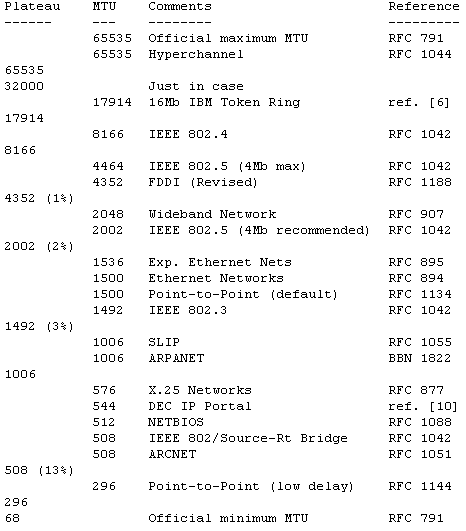
Early implementations of RFC 1191 did not supply the adjacent hop MTU information. Even when this information was supplied, some hosts ignore it. For this case, RFC 1191 besides contains a table that lists the suggested values by which the MTU should be lowered during PMTUD. It is used by hosts in guild to go far more than quickly at a reasonable value for the send MSS and equally shown in the image.
PMTUD is done continually on all packets considering the path between sender and receiver can alter dynamically. Each time a sender receives a "Can't Fragment" ICMP messages it will update the routing information (where it stores the PMTUD).
Ii possible things tin happen during PMTUD:
i. The parcel tin become all the style to the receiver without being fragmented.
Annotation: In guild for a router to protect the CPU against DoS attacks, it throttles the number of ICMP unreachable letters that it would send, to ii per second. Therefore, in this context, if you have a network scenario in which you await that the router would need to respond with more than ii ICMP messages (type = 3, code = four) per second (tin exist different hosts), yous would desire to disable the throttling of ICMP messages with the no ip icmp charge per unit-limit unreachable [df] interface command.
2. The sender tin can go ICMP "Can't Fragment" messages from any (or every) hop along the path to the receiver.
PMTUD is done independently for both directions of a TCP flow. There might be cases where PMTUD in one direction of a period triggers ane of the end stations to lower the send MSS and the other end station keeps the original send MSS because it never sent an IPv4 datagram large enough to trigger PMTUD.
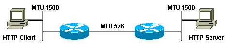
A skilful example of this is the HTTP connection depicted below in Scenario 3. The TCP client sends small packets and the server sends big packets. In this example, merely the server's large packets (greater than 576 bytes) will trigger PMTUD. The customer's packets are small (less than 576 bytes) and will not trigger PMTUD because they exercise not require fragmentation to get across the 576 MTU link.
Scenario 3
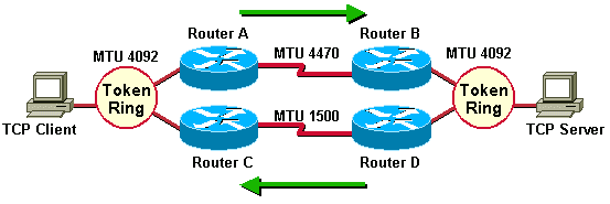
Scenario 4 shows an disproportionate routing example where 1 of the paths has a smaller minimum MTU than the other. Asymmetric routing occurs when unlike paths are taken to send and receive data betwixt two endpoints. In this scenario, PMTUD volition trigger the lowering of the send MSS only in 1 direction of a TCP flow. The traffic from the TCP client to the server flows through Router A and Router B, whereas the return traffic that comes from the server to the client flows through Router D and Router C. When the TCP server sends packets to the client, PMTUD will trigger the server to lower the transport MSS because Router D must fragment the 4092 byte packets before it can transport them to Router C.
The client, on the other mitt, will never receive an ICMP "Destination Unreachable" message with the lawmaking that indicates "fragmentation needed and DF fix" because Router A does not take to fragment packets when it sends them to the server through Router B.
Scenario 4
Annotation: The ip tcp path-mtu-discovery control is used in lodge to enable TCP MTU path discovery for TCP connections initiated past routers (BGP and Telnet for example).
Problems with PMTUD
In that location are three things that can break PMTUD, two of which are uncommon and one of which is common.
-
A router can drop a packet and not send an ICMP bulletin. (Uncommon)
-
A router can generate and send an ICMP message, but the ICMP message gets blocked by a router or firewall betwixt this router and the sender. (Common)
-
A router can generate and ship an ICMP bulletin, but the sender ignores the message. (Uncommon)
The outset and final of the iii bullets here are uncommon and are ordinarily the result of an error, but the middle bullet describes a common problem. People that implement ICMP packet filters tend to cake all ICMP message types rather than only blocking certain ICMP message types. A parcel filter can block all ICMP message types except those that are "unreachable" or "fourth dimension-exceeded." The success or failure of PMTUD hinges upon ICMP unreachable messages getting through to the sender of a TCP/IPv4 packet. ICMP time-exceeded messages are important for other IPv4 issues. An example of such a packet filter, implemented on a router is shown here.
access-listing 101 allow icmp any any unreachable access-list 101 permit icmp any any time-exceeded admission-list 101 deny icmp any any access-list 101 permit ip whatsoever any
There are other techniques that can exist used in order to help alleviate the problem of ICMP being completely blocked.
-
Clear the DF flake on the router and allow fragmentation anyway (This might not be a proficient thought, though. See Issues with IP Fragmentation for more data).
-
Dispense the TCP MSS pick value MSS with the interface control ip tcp adjust-mss <500-1460>.
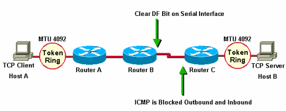
In the side by side scenario, Router A and Router B are in the aforementioned administrative domain. Router C is inaccessible and blocks ICMP, and so PMTUD is cleaved. A workaround for this situation is to articulate the DF flake in both directions on Router B in guild to let fragmentation. This can be done with policy routing. The syntax to clear the DF bit is available in Cisco IOS® Software Release 12.1(six) and subsequently.
interface serial0 ... ip policy route-map clear-df-fleck route-map clear-df-scrap permit x match ip accost 111 set ip df 0 access-list 111 allow tcp any any
Another option is to change the TCP MSS option value on SYN packets that traverse the router (bachelor in Cisco IOS® 12.two(4)T and later). This reduces the MSS pick value in the TCP SYN packet so that information technology is smaller than the value (1460) in the ip tcp accommodate-mss command. The effect is that the TCP sender will ship segments no larger than this value. The IPv4 packet size will be xl bytes larger (1500) than the MSS value (1460 bytes) in order to account for the TCP header (twenty bytes) and the IPv4 header (twenty bytes).
You can accommodate the MSS of TCP SYN packets with the ip tcp adjust-mss control. This syntax will reduce the MSS value on TCP segments to 1460. This command effects traffic both inbound and outbound on interface serial0.
int s0 ip tcp adjust-mss 1460
IPv4 fragmentation issues take go more widespread since IPv4 tunnels take become more widely deployed. The reason that tunnels crusade more fragmentation is because the tunnel encapsulation adds "overhead" to the size of a packet. For instance, the improver of Generic Router Encapsulation (GRE) adds 24 bytes to a packet, and after this increase, the parcel might need to be fragmented considering it is larger than the outbound MTU. In a after section of this document, you will see examples of the kinds of problems that tin arise with tunnels and IPv4 fragmentation.
Common Network Topologies that Need PMTUD
PMTUD is needed in network situations where intermediate links have smaller MTUs than the MTU of the end links. Some common reasons for the existence of these smaller MTU links are:
-
Token Band (or FDDI)-connected end hosts with an Ethernet connectedness between them. The Token Ring (or FDDI) MTUs at the ends are greater than the Ethernet MTU in the eye.
-
PPPoE (oft used with ADSL) needs 8 bytes for its header. This reduces the effective MTU of the Ethernet to 1492 (1500 - viii).
Tunneling protocols like GRE, IPv4sec, and L2TP also need space for their respective headers and trailers. This also reduces the constructive MTU of the outgoing interface.
In the next sections, the bear upon of PMTUD where a tunneling protocol is used somewhere between the two end hosts are studied. Of the three previous cases, this example is the virtually circuitous and covers all of the issues that you might come across in the other cases.
A tunnel is a logical interface on a Cisco router that provides a manner to encapsulate passenger packets within a transport protocol. Information technology is an compages designed to provide services in social club to implement a point-to-indicate encapsulation scheme. Tunneling has these three master components:
-
Passenger protocol (AppleTalk, Banyan VINES, CLNS, DECnet, IPv4, or IPX)
-
Carrier protocol - I of these encapsulation protocols:
-
GRE - Cisco's multiprotocol carrier protocol. Run across RFC 2784 and RFC 1701 for more information.
-
IPv4 in IPv4 tunnels - See RFC 2003 for more than data.
-
-
Send protocol - The protocol used to comport the encapsulated protocol.
The packets shown in this department illustrate the IPv4 tunneling concepts where GRE is the encapsulation protocol and IPv4 is the ship protocol. The rider protocol is also IPv4. In this instance, IPv4 is both the transport and the passenger protocol.
Normal Packet
Tunnel Packet
| IPv4 | GRE | IPv4 | TCP | Telnet |
-
IPv4 is the ship protocol.
-
GRE is the encapsulation protocol.
-
IPv4 is the passenger protocol.
The side by side case shows the encapsulation of IPv4 and DECnet as passenger protocols with GRE as the carrier. This illustrates the fact that the carrier protocol can encapsulate multiple passenger protocols as shown in the prototype.

A network administrator might consider tunneling in a situation where in that location are two discontiguous non-IPv4 networks separated by an IPv4 backbone. If the discontiguous networks run DECnet, the administrator might not want to connect them together by configuring DECnet in the courage. The administrator might non want to permit DECnet routing to consume backbone bandwidth because this could interfere with the performance of the IPv4 network.
A feasible culling is to tunnel DECnet over the IPv4 backbone. Tunneling encapsulates the DECnet packets inside IPv4, and sends them beyond the backbone to the tunnel endpoint where the encapsulation is removed and the DECnet packets can be routed to their destination via DECnet.
Encapsulating traffic inside another protocol provides these advantages:
-
The endpoints utilize private addresses (RFC 1918) and the backbone does not support routing these addresses.
-
Allow Virtual Private Networks (VPNs) across WANs or the Internet.
-
Join together discontiguous multiprotocol networks over a single-protocol courage.
-
Encrypt traffic over the backbone or Internet.
For the rest of the document, IPv4 is used as the passenger protocol and IPv4 as the transport protocol.
Considerations Regarding Tunnel Interfaces
These are considerations when tunneling.
-
Fast switching of GRE tunnels was introduced in Cisco IOS® Release 11.1 and CEF switching was introduced in version 12.0. CEF switching for multipoint GRE tunnels was introduced in version 12.ii(viii)T. Encapsulation and decapsulation at tunnel endpoints were boring operations in before versions of Cisco IOS® when only process switching was supported.
-
There are security and topology problems when tunneling packets. Tunnels tin bypass Access Control Lists (ACLs) and firewalls. If you tunnel through a firewall, you basically bypass the firewall for whatever passenger protocol you lot are tunneling. Therefore, it is recommended to include firewall functionality at the tunnel endpoints in order to enforce whatsoever policy on the passenger protocols.
-
Tunneling might create problems with transport protocols that take limited timers (for example, DECnet) considering of increased latency.
-
Tunneling across environments with different speed links, like fast FDDI rings and through slow 9600-bps phone lines, might introduce packet reordering issues. Some rider protocols function poorly in mixed media networks.
-
Point-to-point tunnels can utilize up the bandwidth on a physical link. If you run routing protocols over multiple signal-to-point tunnels, go on in mind that each tunnel interface has a bandwidth and that the physical interface over which the tunnel runs has a bandwidth. For case, you lot would desire to set the tunnel bandwidth to 100 Kb if there were 100 tunnels running over a 10 Mb link. The default bandwidth for a tunnel is 9Kb.
-
Routing protocols might prefer a tunnel over a real link because the tunnel might deceptively appear to exist a i-hop link with the everyman cost path, although it actually involves more hops and is really more than plush than some other path. This can be mitigated with proper configuration of the routing protocol. You might want to consider running a different routing protocol over the tunnel interface than the routing protocol running on the physical interface.
-
Issues with recursive routing tin can exist avoided by configuring appropriate static routes to the tunnel destination. A recursive road is when the best path to the tunnel destination is through the tunnel itself. This situation causes the tunnel interface to bounce up and downward. You will see this error when there is a recursive routing problem.
%TUN-RECURDOWN Interface Tunnel 0 temporarily disabled due to recursive routing
Router as PMTUD Participant at Endpoint of Tunnel
The router has two unlike PMTUD roles to play when it is the endpoint of a tunnel.
-
In the first role, the router is the forwarder of a host packet. For PMTUD processing, the router needs to cheque the DF chip and packet size of the original data parcel and take appropriate action when necessary.
-
The second role comes into play later the router has encapsulated the original IPv4 bundle inside the tunnel parcel. At this phase, the router acts more similar a host with respect to PMTUD and in regards to the tunnel IPv4 packet.
Lets have a wait at what happens when the router acts in the showtime office, a router that frontwards host IPv4 packets, with respect to PMTUD. This office comes into play earlier the router encapsulates the host IPv4 packet inside the tunnel bundle.
If the router participates every bit the forwarder of a host bundle it will complete these actions:
-
Cheque whether the DF scrap is ready
-
Cheque what size packet the tunnel can arrange
-
Fragment (if packet is too large and DF bit is not set), encapsulate fragments and send; or
-
Drop the packet (if packet is too big and DF bit is gear up) and send an ICMP bulletin to the sender
-
Encapsulate (if package is not too large) and transport
Generically, at that place is a choice of encapsulation and then fragmentation (send 2 encapsulation fragments) or fragmentation and so encapsulation (ship two encapsulated fragments).
Some examples that describe the mechanics of IPv4 packet encapsulation and fragmentation and two scenarios that evidence the interaction of PMTUD and packets that traverse example networks are detailed in this department.
The first example shows what happens to a package when the router (at the tunnel source) acts in the role of forwarding router. Retrieve that to procedure PMTUD, the router needs to check the DF chip and packet size of the original data packet and take advisable action. This examples uses GRE encapsulation for the tunnel. Every bit can be seen, GRE does fragmentation before encapsulation. Subsequently examples show scenarios in which fragmentation is done after encapsulation.
In Example 1, the DF chip is not set (DF = 0) and the GRE tunnel IPv4 MTU is 1476 (1500 - 24).
Example 1
1. The forwarding router (at the tunnel source) receives a 1500-byte datagram with the DF chip articulate (DF = 0) from the sending host. This datagram is composed of a 20-byte IP header plus a 1480 byte TCP payload.
| IPv4 | 1480 bytes TCP + data |
ii. Because the bundle is likewise large for the IPv4 MTU later the GRE overhead (24 bytes) is added, the forwarding router breaks the datagram into two fragments of 1476 (twenty bytes IPv4 header + 1456 bytes IPv4 payload) and 44 bytes (20 bytes of IPv4 header + 24 bytes of IPv4 payload) and so after the GRE encapsulation is added, the packet will non be larger than the approachable physical interface MTU.
| IP0 | 1456 bytes TCP + information |
iii. The forwarding router adds GRE encapsulation, which includes a 4-byte GRE header plus a xx-byte IPv4 header, to each fragment of the original IPv4 datagram. These 2 IPv4 datagrams at present accept a length of 1500 and 68 bytes and these datagrams are seen every bit private IPv4 datagrams, not as fragments.
| IPv4 | GRE | IP0 | 1456 bytes TCP + data |
| IPv4 | GRE | IP1 | 24 bytes data |
4. The tunnel destination router removes the GRE encapsulation from each fragment of the original datagram, which leaves 2 IPv4 fragments of lengths 1476 and 24 bytes. These IPv4 datagram fragments are forwarded separately by this router to the receiving host.
| IP0 | 1456 bytes TCP + data |
5. The receiving host reassembles these two fragments into the original datagram.
| IPv4 | 1480 bytes TCP + data |
Scenario 5 depicts the role of the forwarding router in the context of a network topology.
In this example, the router acts in the aforementioned role of forwarding router, simply this time the DF bit is set (DF = 1).
Example 2
ane. The forwarding router at the tunnel source receives a 1500-byte datagram with DF = i from the sending host.
| IPv4 | 1480 bytes TCP + information |
2. Since the DF bit is set, and the datagram size (1500 bytes) is greater than the GRE tunnel IPv4 MTU (1476), the router volition drop the datagram and send an "ICMP fragmentation needed only DF bit fix" message to the source of the datagram. The ICMP bulletin will alert the sender that the MTU is 1476.
3. The sending host receives the ICMP message, and when it resends the original information it uses a 1476-byte IPv4 datagram.
| IPv4 | 1456 bytes TCP + information |
4. This IPv4 datagram length (1476 bytes) is now equal in value to the GRE tunnel IPv4 MTU then the router adds the GRE encapsulation to the IPv4 datagram.
| IPv4 | GRE | IPv4 | 1456 bytes TCP + data |
five. The receiving router (at the tunnel destination) removes the GRE encapsulation of the IPv4 datagram and sends it to the receiving host.
| IPv4 | 1456 bytes TCP + information |
Now, y'all can look at what happens when the router acts in the second office as a sending host with respect to PMTUD and in regards to the tunnel IPv4 packet. Remember that this role comes into play later the router has encapsulated the original IPv4 packet within the tunnel parcel.
Note: Past default, a router does not do PMTUD on the GRE tunnel packets that it generates. The tunnel path-mtu-discovery command can be used to turn on PMTUD for GRE-IPv4 tunnel packets.
Case iii shows what happens when the host sends IPv4 datagrams that are pocket-size enough to fit within the IPv4 MTU on the GRE Tunnel interface. The DF bit in this case can be either set or clear (1 or 0). The GRE tunnel interface does not have the tunnel path-mtu-discovery command configured so the router will not do PMTUD on the GRE-IPv4 package.
Instance three
1. The forwarding router at the tunnel source receives a 1476-byte datagram from the sending host.
| IPv4 | 1456 bytes TCP + data |
two. This router encapsulates the 1476-byte IPv4 datagram within GRE to get a 1500-byte GRE IPv4 datagram. The DF flake in the GRE IPv4 header volition be clear (DF = 0). This router then forrad this package to the tunnel destination.
| IPv4 | GRE | IPv4 | 1456 bytes TCP + data |
3. Assume in that location is a router between the tunnel source and destination with a link MTU of 1400. This router will fragment the tunnel packet since the DF bit is clear (DF = 0). Remember that this example fragments the outermost IPv4, so the GRE, inner IPv4, and TCP headers will but show up in the start fragment.
| IP0 | GRE | IP | 1352 bytes TCP + data |
4. The tunnel destination router must reassemble the GRE tunnel bundle.
| IP | GRE | IP | 1456 bytes TCP + data |
5. Later on the GRE tunnel packet is reassembled, the router removes the GRE IPv4 header and sends the original IPv4 datagram on its fashion.
| IPv4 | 1456 Bytes TCP + data |
The next example shows what happens when the router acts in the part of a sending host with respect to PMTUD and in regards to the tunnel IPv4 bundle. This fourth dimension the DF chip is set up (DF = i) in the original IPv4 header and the tunnel path-mtu-discovery control has been configured so that the DF bit will be copied from the inner IPv4 header to the outer (GRE + IPv4) header.
Example four
1. The forwarding router at the tunnel source receives a 1476-byte datagram with DF = ane from the sending host.
| IPv4 | 1456 bytes TCP + data |
2. This router encapsulates the 1476-byte IPv4 datagram inside GRE to get a 1500-byte GRE IPv4 datagram. This GRE IPv4 header will have the DF bit ready (DF = 1) since the original IPv4 datagram had the DF bit ready. This router so forwards this packet to the tunnel destination.
| IPv4 | GRE | IPv4 | 1456 bytes TCP |
3. Again, presume there is a router between the tunnel source and destination with a link MTU of 1400. This router will not fragment the tunnel packet since the DF chip is set up (DF=one). This router must drop the packet and send an ICMP error message to the tunnel source router, since that is the source IPv4 address on the package.
four. The forwarding router at the tunnel source receives this "ICMP" error message and it will lower the GRE tunnel IPv4 MTU to 1376 (1400 - 24). The side by side time the sending host retransmits the information in a 1476-byte IPv4 packet, this package tin can be too large and this router will ship an "ICMP" error message to the sender with a MTU value of 1376. When the sending host retransmits the data, it will send it in a 1376-byte IPv4 parcel and this packet will make information technology through the GRE tunnel to the receiving host.
Scenario 5
This scenario illustrates GRE fragmentation. Remember that you lot fragment before encapsulation for GRE, then do PMTUD for the data parcel, and the DF bit is not copied when the IPv4 packet is encapsulated by GRE. In this scenario, the DF bit is not gear up. The GRE tunnel interface IPv4 MTU is, by default, 24 bytes less than the physical interface IPv4 MTU, so the GRE interface IPv4 MTU is 1476 as shown in the image.

- The sender sends a 1500-byte packet (20 byte IPv4 header + 1480 bytes of TCP payload).
- Since the MTU of the GRE tunnel is 1476, the 1500-byte packet is broken into two IPv4 fragments of 1476 and 44 bytes, each in anticipation of the additional 24 byes of GRE header.
- The 24 bytes of GRE header is added to each IPv4 fragment. Now the fragments are 1500 (1476 + 24) and 68 (44 + 24) bytes each.
- The GRE + IPv4 packets that contain the two IPv4 fragments are forwarded to the GRE tunnel peer router.
- The GRE tunnel peer router removes the GRE headers from the two packets.
- This router forrard the 2 packets to the destination host.
- The destination host reassembles the IPv4 fragments back into the original IPv4 datagram.
Scenario half dozen
This scenario is similar to Scenario v, simply this fourth dimension the DF bit is gear up. In Scenario 6, the router is configured to do PMTUD on GRE + IPv4 tunnel packets with the tunnel path-mtu-discovery command, and the DF bit is copied from the original IPv4 header to the GRE IPv4 header. If the router receives an ICMP error for the GRE + IPv4 packet, information technology reduces the IPv4 MTU on the GRE tunnel interface. Once more, remember that the GRE Tunnel IPv4 MTU is fix to 24 bytes less than the concrete interface MTU by default, so the GRE IPv4 MTU here is 1476. Also notice that there is a 1400 MTU link in the GRE tunnel path as shown in the epitome.

- The router receives a 1500-byte bundle (20 byte IPv4 header + 1480 TCP payload), and it drops the parcel. The router drops the parcel because information technology is larger than the IPv4 MTU (1476) on the GRE tunnel interface.
- The router sends an ICMP error to the sender telling it that the next-hop MTU is 1476. The host will record this information, unremarkably as a host route for the destination in its routing table.
- The sending host uses a 1476-byte parcel size when it resends the data. The GRE router adds 24 bytes of GRE encapsulation and ships out a 1500-byte package.
- The 1500-byte packet cannot traverse the 1400-byte link, and then it is dropped by the intermediate router.
- The intermediate router sends an ICMP (type = 3, code = four) to the GRE router with a adjacent-hop MTU of 1400. The GRE router reduces this to 1376 (1400 - 24) and sets an internal IPv4 MTU value on the GRE interface. This change can only be seen when using the debug tunnel control; it cannot exist seen in the output from the evidence ip interface tunnel<#> command.
- The next time the host resends the 1476-byte packet, the GRE router will drop the packet, since it is larger than the current IPv4 MTU (1376) on the GRE tunnel interface.
- The GRE router will transport some other ICMP (type = 3, lawmaking = 4) to the sender with a next-hop MTU of 1376 and the host volition update its electric current information with new value.
- The host once again resends the data, just now in a smaller 1376-byte bundle, GRE will add 24 bytes of encapsulation and forrad it on. This time the package will make it to the GRE tunnel peer, where the packet will exist decapsulated and sent to the destination host.
Note: If the tunnel path-mtu-discovery command was not configured on the forwarding router in this scenario, and the DF bit was fix in the packets forwarded through the GRE tunnel, Host 1 would withal succeed in sending TCP/IPv4 packets to Host two, but they would get fragmented in the middle at the 1400 MTU link. Too the GRE tunnel peer would have to reassemble them before information technology could decapsulate and forwards them on.
The IPv4 Security (IPv4sec) Protocol is a standards-based method that provides privacy, integrity, and authenticity to information transferred across IPv4 networks. IPv4sec provides IPv4 network-layer encryption. IPv4sec lengthens the IPv4 parcel by adding at least one IPv4 header (tunnel manner). The added header(due south) varies in length dependent on the IPv4sec configuration mode but they exercise not exceed ~58 bytes (Encapsulating Security Payload (ESP) and ESP authentication (ESPauth)) per package.
IPv4sec has 2 modes, tunnel mode and transport mode.
- Tunnel mode is the default style. With tunnel manner, the unabridged original IPv4 bundle is protected (encrypted, authenticated, or both) and encapsulated past the IPv4sec headers and trailers. And then a new IPv4 header is prepended to the packet, which specifies the IPv4sec endpoints (peers) as the source and destination. Tunnel mode tin be used with any unicast IPv4 traffic and must be used if IPv4sec protects traffic from hosts backside the IPv4sec peers. For example, tunnel manner is used with Virtual Private Networks (VPNs) where hosts on one protected network send packets to hosts on a different protected network via a pair of IPv4sec peers. With VPNs, the IPv4sec "tunnel" protects the IPv4 traffic betwixt hosts by encrypting this traffic between the IPv4sec peer routers.
- With transport way (configured with the subcommand, mode transport, on the transform definition), only the payload of the original IPv4 packet is protected (encrypted, authenticated, or both). The payload is encapsulated past the IPv4sec headers and trailers. The original IPv4 headers remain intact, except that the IPv4 protocol field is changed to exist ESP (50), and the original protocol value is saved in the IPv4sec trailer to be restored when the bundle is decrypted. Transport style is used simply when the IPv4 traffic to be protected is between the IPv4sec peers themselves, the source and destination IPv4 addresses on the packet are the aforementioned as the IPv4sec peer addresses. Unremarkably IPv4sec send style is but used when some other tunneling protocol (similar GRE) is used to start encapsulate the IPv4 data packet, and then IPv4sec is used to protect the GRE tunnel packets.
IPv4sec always does PMTUD for data packets and for its own packets. There are IPv4sec configuration commands to modify PMTUD processing for the IPv4sec IPv4 package, IPv4sec tin articulate, set up, or re-create the DF chip from the data package IPv4 header to the IPv4sec IPv4 header. This is called the "DF Bit Override Functionality" feature.
Note: Yous actually desire to avoid fragmentation after encapsulation when you do hardware encryption with IPv4sec. Hardware encryption tin can give you lot throughput of nigh 50 Mbs which depends on the hardware, but if the IPv4sec packet is fragmented you loose 50 to ninety percent of the throughput. This loss is because the fragmented IPv4sec packets are process-switched for reassembly and then handed to the Hardware encryption engine for decryption. This loss of throughput can bring hardware encryption throughput down to the functioning level of software encryption (ii-10 Mbs).
Scenario 7
This scenario depicts IPv4sec fragmentation in action. In this scenario, the MTU forth the entire path is 1500. In this scenario, the DF bit is non set.
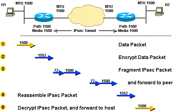
- The router receives a 1500-byte packet (xx-byte IPv4 header + 1480 bytes TCP payload) destined for Host 2.
- The 1500-byte packet is encrypted by IPv4sec and 52 bytes of overhead are added (IPv4sec header, trailer, and additional IPv4 header). Now IPv4sec needs to send a 1552-byte packet. Since the outbound MTU is 1500, this packet will have to be fragmented.
- 2 fragments are created out of the IPv4sec packet. During fragmentation, an additional 20-byte IPv4 header is added for the second fragment, resulting in a 1500-byte fragment and a 72-byte IPv4 fragment.
- The IPv4sec tunnel peer router receives the fragments, strips off the additional IPv4 header and coalesces the IPv4 fragments dorsum into the original IPv4sec packet. Then IPv4sec decrypts this packet.
- The router and so forwards the original 1500-byte data packet to Host two.
Scenario 8
This scenario is similar to Scenario 6 except that in this case the DF chip is set in the original data package and in that location is a link in the path between the IPv4sec tunnel peers that has a lower MTU than the other links. This scenario demonstrates how the IPv4sec peer router performs both PMTUD roles, equally described in the The Router as a PMTUD Participant at the Endpoint of a Tunnel section.
You will encounter in this scenario how the IPv4sec PMTU changes to a lower value as the outcome of the need for fragmentation. Retrieve that the DF bit is copied from the inner IPv4 header to the outer IPv4 header when IPv4sec encrypts a bundle. The media MTU and PMTU values are stored in the IPv4sec Security Association (SA). The media MTU is based on the MTU of the outbound router interface and the PMTU is based on the minimum MTU seen on the path between the IPv4sec peers. Retrieve that IPv4sec encapsulates/encrypts the packet before information technology attempts to fragment it as shown in the epitome.
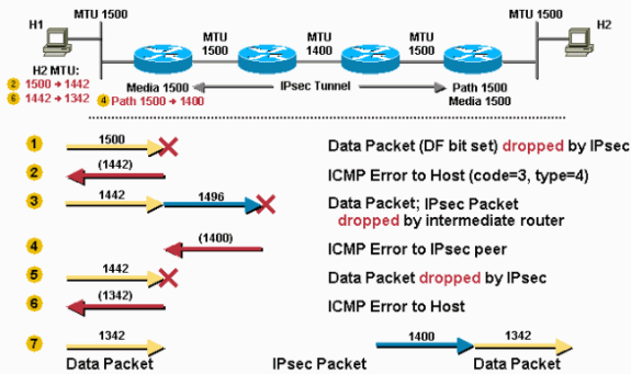
- The router receives a 1500-byte packet and drops information technology because the IPv4sec overhead, when added, will make the bundle larger than the PMTU (1500).
- The router sends an ICMP message to Host i telling it that the side by side-hop MTU is 1442 (1500 - 58 = 1442). This 58 bytes is the maximum IPv4sec overhead when using IPv4sec ESP and ESPauth. The existent IPv4sec overhead may exist as much every bit seven bytes less than this value. Host one records this information, usually as a host route for the destination (Host 2), in its routing tabular array.
- iii. Host 1 lowers its PMTU for Host 2 to 1442, so Host ane will ship smaller (1442 byte) packets when information technology retransmits the data to Host 2. The router receives the 1442-byte parcel and IPv4sec adds 52 bytes of encryption overhead and so the resulting IPv4sec packet is 1496 bytes. Considering this packet has the DF bit set in its header it gets dropped by the middle router with the 1400-byte MTU link.
- The middle router that dropped the packet sends an ICMP bulletin to the sender of the IPv4sec packet (the outset router) telling information technology that the next-hop MTU is 1400 bytes. This value is recorded in the IPv4sec SA PMTU.
- The next time Host 1 retransmits the 1442-byte packet (information technology didn't receive an acquittance for it), the IPv4sec will drop the packet. Again the router will drop the packet because the IPv4sec overhead, when added to the bundle, will make it larger than the PMTU (1400).
- The router sends an ICMP bulletin to Host 1 telling it that the next-hop MTU is at present 1342. (1400 - 58 = 1342). Host ane will once more record this information.
- When Host 1 once more retransmits the data, it will use the smaller size parcel (1342). This packet will not require fragmentation and will make it through the IPv4sec tunnel to Host 2.
More circuitous interactions for fragmentation and PMTUD occur when IPv4sec is used in gild to encrypt GRE tunnels. IPv4sec and GRE are combined in this way considering IPv4sec does not support IPv4 multicast packets, which means that you cannot run a dynamic routing protocol over the IPv4sec VPN Network. GRE tunnels exercise back up multicast, so a GRE tunnel can be used to first encapsulate the dynamic routing protocol multicast packet in a GRE IPv4 unicast parcel that can then exist encrypted by IPv4sec. When doing this, IPv4sec is often deployed in transport mode on top of GRE considering the IPv4sec peers and the GRE tunnel endpoints (the routers) are the same, and transport-mode will relieve 20 bytes of IPv4sec overhead.
One interesting case is when an IPv4 packet has been split into two fragments and encapsulated by GRE. In this case IPv4sec volition see two independent GRE + IPv4 packets. Often in a default configuration one of these packets will be large enough that it volition need to exist fragmented afterwards it has been encrypted. The IPv4sec peer will take to reassemble this bundle before decryption. This "double fragmentation" (once before GRE and again after IPv4sec) on the sending router increases latency and lowers throughput. Besides, reassembly is procedure-switched, so there will exist a CPU hitting on the receiving router whenever this happens.
This situation can be avoided by setting the "ip mtu" on the GRE tunnel interface depression enough to take into account the overhead from both GRE and IPv4sec (by default the GRE tunnel interface "ip mtu" is set up to the outgoing real interface MTU - GRE overhead bytes).
This table lists the suggested MTU values for each tunnel/mode combination assuming the approachable physical interface has an MTU of 1500.
| Tunnel Combination | Specific MTU Needed | Recommended MTU |
| GRE + IPv4sec (Transport mode) | 1440 bytes | 1400 bytes |
| GRE + IPv4sec (Tunnel mode) | 1420 bytes | 1400 bytes |
Notation: The MTU value of 1400 is recommended considering it covers the most common GRE + IPv4sec mode combinations. Also, there is no discernable downside to allowing for an actress 20 or 40 bytes overhead. It is easier to remember and set one value and this value covers virtually all scenarios.
Scenario 9
IPv4sec is deployed on top of GRE. The outgoing physical MTU is 1500, the IPv4sec PMTU is 1500, and the GRE IPv4 MTU is 1476 (1500 - 24 = 1476). Considering of this, TCP/IPv4 packets will exist fragmented twice, once before GRE and once after IPv4sec. The package will be fragmented before GRE encapsulation and one of these GRE packets volition exist fragmented again after IPv4sec encryption.
Configuring "ip mtu 1440" (IPv4sec Transport mode) or "ip mtu 1420" (IPv4sec Tunnel manner) on the GRE tunnel would remove the possibility of double fragmentation in this scenario.
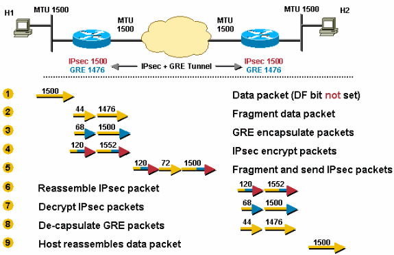
- The router receives a 1500-byte datagram.
- Before encapsulation, GRE fragments the 1500-byte packet into two pieces, 1476 (1500 - 24 = 1476) and 44 (24 data + 20 IPv4 header) bytes.
- GRE encapsulates the IPv4 fragments, which adds 24 bytes to each packet. This results in 2 GRE + IPv4sec packets of 1500 (1476 + 24 = 1500) and 68 (44 + 24) bytes each.
- IPv4sec encrypts the two packets, adding 52 byes (IPv4sec tunnel-mode) of encapsulation overhead to each, in order to give a 1552-byte and a 120-byte packet.
- The 1552-byte IPv4sec packet is fragmented by the router because it is larger than the outbound MTU (1500). The 1552-byte packet is split into pieces, a 1500-byte packet and a 72-byte packet (52 bytes "payload" plus an additional 20-byte IPv4 header for the 2nd fragment). The three packets 1500-byte, 72-byte, and 120-byte packets are forwarded to the IPv4sec + GRE peer.
- The receiving router reassembles the two IPv4sec fragments (1500 bytes and 72 bytes) in club to go the original 1552-byte IPv4sec + GRE packet. Nix needs to be done to the 120-byte IPv4sec + GRE packet.
- IPv4sec decrypts both 1552-byte and 120-byte IPv4sec + GRE packets in gild to get 1500-byte and 68-byte GRE packets.
- GRE decapsulates the 1500-byte and 68-byte GRE packets in order to get 1476-byte and 44-byte IPv4 parcel fragments. These IPv4 parcel fragments are forwarded to the destination host.
- Host ii reassembles these IPv4 fragments in order to get the original 1500-byte IPv4 datagram.
Scenario 10 is like to Scenario 8 except there is a lower MTU link in the tunnel path. This is a worst case scenario for the kickoff packet sent from Host 1 to Host 2. After the last step in this scenario, Host one sets the correct PMTU for Host 2 and all is well for the TCP connections betwixt Host ane and Host 2. TCP flows between Host 1 and other hosts (reachable via the IPv4sec + GRE tunnel) volition only accept to become through the last three steps of Scenario ten.
In this scenario, the tunnel path-mtu-discovery command is configured on the GRE tunnel and the DF bit is gear up on TCP/IPv4 packets that originate from Host i.
Scenario 10
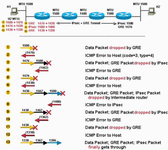
- The router receives a 1500-byte parcel. This parcel is dropped by GRE because GRE cannot fragment or forward the packet because the DF bit is ready, and the parcel size exceeds the outbound interface "ip mtu" after adding the GRE overhead (24 bytes).
- The router sends an ICMP message to Host 1 in order to allow it know that the next-hop MTU is 1476 (1500 - 24 = 1476).
- Host ane changes its PMTU for Host 2 to 1476 and sends the smaller size when information technology retransmits the packet. GRE encapsulates it and easily the 1500-byte packet to IPv4sec. IPv4sec drops the package because GRE has copied the DF bit (prepare) from the inner IPv4 header, and with the IPv4sec overhead (maximum 38 bytes), the packet is too large to forrad out the physical interface.
- IPv4sec sends an ICMP bulletin to GRE which indicates that the next-hop MTU is 1462 bytes (since a maximum 38 bytes will be added for encryption and IPv4 overhead). GRE records the value 1438 (1462 - 24) as the "ip mtu" on the tunnel interface.
- Note: This change in value is stored internally and cannot exist seen in the output of the prove ip interface tunnel<#> control. Y'all will only see this change if y'all plough apply the debug tunnel command.
- The side by side time Host 1 retransmits the 1476-byte packet, GRE drops it.
- The router sends an ICMP bulletin to Host 1 which indicates that 1438 is the side by side-hop MTU.
- Host ane lowers the PMTU for Host 2 and retransmits a 1438-byte packet. This time, GRE accepts the package, encapsulates information technology, and easily it off to IPv4sec for encryption. The IPv4sec packet is forwarded to the intermediate router and dropped considering it has an outbound interface MTU of 1400.
- The intermediate router sends an ICMP bulletin to IPv4sec which tells it that the side by side-hop MTU is 1400. This value is recorded by IPv4sec in the PMTU value of the associated IPv4sec SA.
- When Host one retransmits the 1438-byte package, GRE encapsulates it and hands it to IPv4sec. IPv4sec drops the packet because it has changed its ain PMTU to 1400.
- IPv4sec sends an ICMP fault to GRE which indicates that the next-hop MTU is 1362, and GRE records the value 1338 internally.
- When Host one retransmits the original packet (because it did not receive an acquittance), GRE drops it.
- The router sends an ICMP message to Host ane which indicates the next-hop MTU is 1338 (1362 - 24 bytes). Host i lowers its PMTU for Host 2 to 1338.
- Host 1 retransmits a 1338-byte packet and this fourth dimension information technology tin finally become all the way through to Host 2.
Configuring the tunnel path-mtu-discovery command on a tunnel interface can assistance GRE and IPv4sec interaction when they are configured on the same router. Remember that without the tunnel path-mtu-discovery command configured, the DF bit would e'er be cleared in the GRE IPv4 header. This allows the GRE IPv4 packet to be fragmented even though the encapsulated data IPv4 header had the DF bit ready, which normally would not let the package to be fragmented.
If the tunnel path-mtu-discovery command is configured on the GRE tunnel interface, this will happen.
- GRE will copy the DF scrap from the data IPv4 header to the GRE IPv4 header.
- If the DF bit is prepare in the GRE IPv4 header and the package will be "too large" later IPv4sec encryption for the IPv4 MTU on the physical approachable interface, then IPv4sec will drib the packet and notify the GRE tunnel to reduce its IPv4 MTU size.
- IPv4sec does PMTUD for its own packets and if the IPv4sec PMTU changes (if it is reduced), and so IPv4sec does non immediately notify GRE, simply when some other "also large" packet comes thorough, then the process in step two occurs.
- GRE's IPv4 MTU is now smaller, so information technology will drop any data IPv4 packets with the DF flake gear up that are at present likewise large and send an ICMP message to the sending host.
The tunnel path-mtu-discovery control helps the GRE interface fix its IPv4 MTU dynamically, rather than statically with the ip mtu control. Information technology is really recommended that both commands are used. The ip mtu command is used to provide room for the GRE and IPv4sec overhead relative to the local physical approachable interface IPv4 MTU. The tunnel path-mtu-discovery command allows the GRE tunnel IPv4 MTU to be further reduced if there is a lower IPv4 MTU link in the path betwixt the IPv4sec peers.
Here are some of the things you tin can practice if you lot have problems with PMTUD in a network where there are GRE + IPv4sec tunnels configured.
This list begins with the well-nigh desirable solution.
- Set the problem with PMTUD non working, which is normally acquired by a router or firewall that blocks ICMP.
- Employ the ip tcp arrange-mss command on the tunnel interfaces so that the router will reduce the TCP MSS value in the TCP SYN packet. This will aid the two end hosts (the TCP sender and receiver) to use packets pocket-sized plenty so that PMTUD is not needed.
- Utilise policy routing on the ingress interface of the router and configure a route map to articulate the DF fleck in the data IPv4 header before it gets to the GRE tunnel interface. This will allow the data IPv4 packet to be fragmented earlier GRE encapsulation.
- Increment the "ip mtu" on the GRE tunnel interface to be equal to the outbound interface MTU. This will let the data IPv4 packet to be GRE encapsulated without fragmenting it kickoff. The GRE packet volition then be IPv4sec encrypted and then fragmented to get out the physical outbound interface. In this instance you would non configure tunnel path-mtu-discovery command on the GRE tunnel interface. This can dramatically reduce the throughput because IPv4 package reassembly on the IPv4sec peer is done in process-switching mode.
- IP Routing Back up Page
- IPSec (IP Security Protocol) Support Page
- IPSec Overhead Reckoner (Summate Package Size with IPSec Encapsulation Protocols)
- RFC 1191 Path MTU Discovery
- RFC 1063 IP MTU Discovery Options
- RFC 791 Internet Protocol
- RFC 793 Transmission Control Protocol
- RFC 879 The TCP Maximum Segment Size and Related Topics
- RFC 1701 Generic Routing Encapsulation (GRE)
- RFC 1241 A Scheme for an Net Encapsulation Protocol
- RFC 2003 IP Encapsulation within IP
- Technical Support & Documentation - Cisco Systems
0 Response to "Which Two Gre Features Can You Configure to Prevent Fragmentation (Choose Two)"
Post a Comment